Turning a pencil sketch into a 3D printed object is one of those processes that feels almost magical at first, but it’s built on a series of logical, careful steps.
Artists, engineers, product designers, and hobbyists all rely on this workflow when they want to bring concepts from paper into the real world.
The challenge is that sketches are loose and expressive, while printers demand precision. The solution is a structured workflow that balances creativity with technical accuracy.
Why a Structured Workflow Makes the Difference
A hand drawn sketch carries charm and spontaneity, but it rarely has the geometry a 3D printer can understand.
Without a structured process, you risk wasted material, failed prints, or models that simply don’t resemble your original vision. That’s why the conversion needs to be methodical.
When you follow a clear workflow:
- Your sketch retains its unique personality while gaining technical precision.
- File preparation becomes more efficient, saving time on revisions.
- You avoid common errors like non-manifold geometry, thin walls, or scaling issues.
In short, the workflow is what bridges the imagination of the sketch and the technical reality of additive manufacturing.
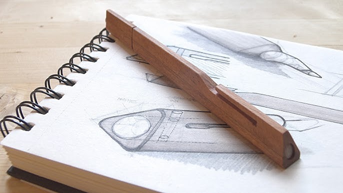
Capturing the Sketch in Digital Form
The first tangible step is digitization. Whether you’re drawing a mechanical part, a piece of jewelry, or a character design, the original sketch needs to enter the digital world cleanly.
A scanner works best because it produces flat, distortion-free images. If you only have a camera, make sure the lighting is even, the page is flat, and the photo is taken straight on.
Extra shadows, angles, or warped paper can introduce errors later when you trace the drawing.
At this stage, a little preparation goes a long way. Sketch with bold, consistent lines and avoid shading that can confuse vectorization tools. Think of it as preparing your sketch to become a blueprint.
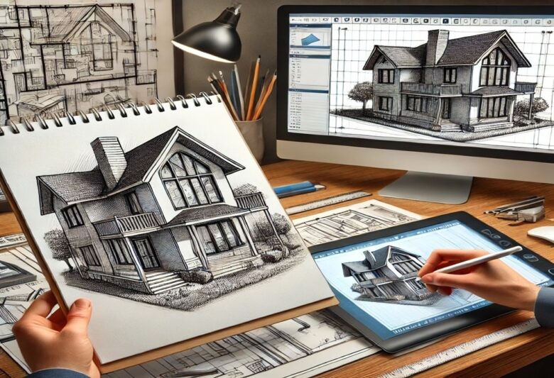
Turning the Image into a Usable Reference

Once the sketch is digitized, you’ll need to make it usable inside a 3D modeling program. A scanned JPEG alone won’t cut it. Most designers convert the image into vectors or set it up as a reference plane.
- Vectorization tools like Adobe Illustrator or Inkscape let you trace your lines into smooth, scalable paths.
- CAD imports allow you to place the sketch directly as a background reference, then manually trace with precision tools.
If speed is your priority, automated solutions come into play. An image to 3d service provides a direct path from your drawing to a base 3D model. It doesn’t eliminate the need for refinement, but it accelerates the early stages and keeps you focused on design rather than repetitive digital tracing.
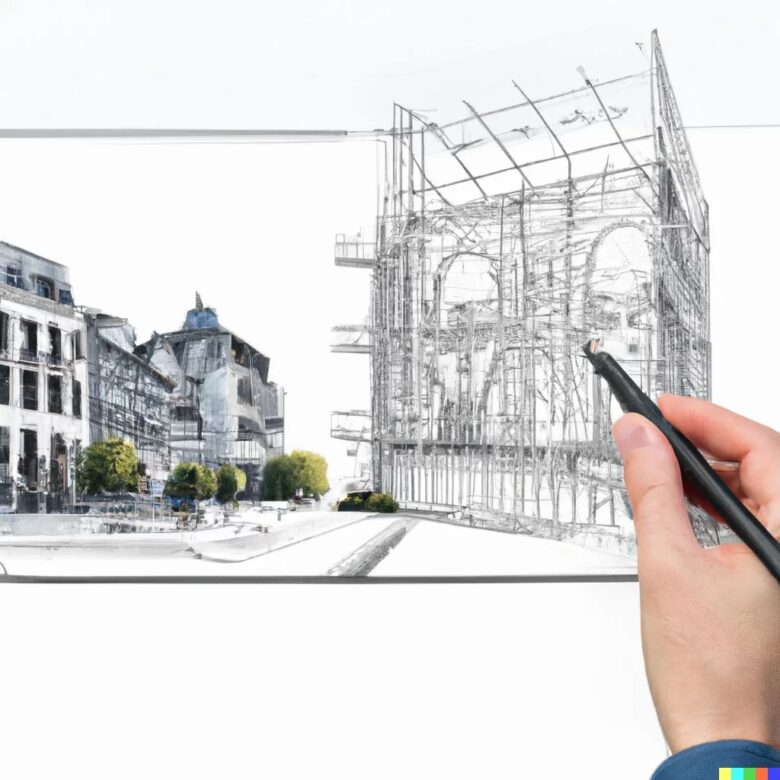
Building the Model in CAD
This is where the sketch stops being just a picture and begins to exist in three dimensions. The choice of CAD software depends on what you’re making:
- Fusion 360 / SolidWorks: Best for engineered parts, assemblies, and items needing exact tolerances.
- Blender: Excellent for artistic and organic forms like characters, jewelry, or decorative pieces.
- TinkerCAD: Beginner-friendly, browser-based, and useful for simple models.
In practice, the process involves importing the sketch or vector, aligning it on a reference plane, and then constructing geometry using tools like extrusion, revolving, or lofting. The early model is rarely perfect. Instead, it’s the scaffolding from which precision will emerge.
Refining, Correcting, and Adding Detail
Here’s where the bulk of the work often lies. A raw CAD build tends to look stiff or unfinished. Refinement is about smoothing, correcting, and ensuring the model won’t fail in the printer.
Some common refinements include:
- Scaling and dimension checks to ensure it matches real-world use.
- Wall thickness adjustments so the object doesn’t break easily.
- Smoothing surfaces to avoid jagged prints.
- Adding functional elements such as joints, screw holes, or snap-fits if the object needs assembly.
Think of this stage as sculpting. The original sketch gave you a silhouette, but refinement ensures the 3D object behaves as it should when printed.
Converting to Printable Format
When the model looks complete, you’ll export it to STL or OBJ—formats that slicing software can interpret. But this is not just a “Save As” step. Exporting without checking for geometry errors can lead to frustrating failures.
Before export, always verify:
- The model is watertight with no gaps.
- It is manifold, meaning every edge connects exactly two faces.
- Orientation is correct so the printer builds it logically.
Repair tools like Meshmixer or Netfabb are excellent for catching these issues automatically.
Skipping this check is one of the most common reasons newcomers end up with unprintable files.
Running Tests in Slicer Software
Your STL or OBJ file now goes into slicer software such as Cura, PrusaSlicer, or Simplify3D. This stage reveals how the printer will interpret your model.
The slicer generates toolpaths and previews every layer.
This is where you can make critical decisions:
- Rotate the model for better support and shorter print times.
- Adjust infill percentage to balance strength and material usage.
- Add supports for overhangs that can’t stand alone.
Treat slicing like a dry rehearsal before the live performance. If the slicer preview shows gaps, awkward supports, or excessive print time, it’s better to fix it now rather than waste filament.
Prototyping and Iterating
Few models are “print once and done.” Prototyping is normal and expected. That first print might reveal that the tolerances are off, or the design doesn’t look as natural in 3D as it did on paper. Adjusting the CAD model and reprinting is part of the cycle.
This iterative approach is valuable because it ties digital design to physical reality
. You’ll refine not just geometry, but also your own skills with each pass. Professional designers often plan for at least two or three iterations before signing off on a final version.
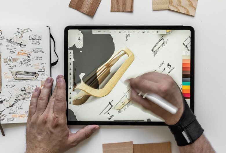
Practical Tips for Smoother Conversions
Some advice makes the entire workflow easier to manage:
- Start with bold sketches: thin, faint lines complicate vectorization.
- Work incrementally: save CAD files at different stages so you can roll back easily.
- Respect printer limitations: know the layer height, build volume, and nozzle size you’re working with.
- Simplify where possible: fewer surfaces mean faster slicing and fewer errors.
Conclusion: From Sketch to Reality
The journey from hand drawn sketch to 3D printed object is a mix of artistry and engineering. Each step—digitization, vectorization, CAD construction, refinement, slicing, and prototyping—adds clarity and reliability to your design.
By respecting the workflow, you ensure the charm of your sketch is preserved while meeting the technical demands of 3D printing.
In the end, this process is what makes 3D printing so powerful: it gives ideas drawn on paper the chance to become physical objects you can hold, test, and use.